Rolling Robots
robotic video production and follow focus


-
Follow focus rig v3 -
Follow focus rig v1 -

Test setup -
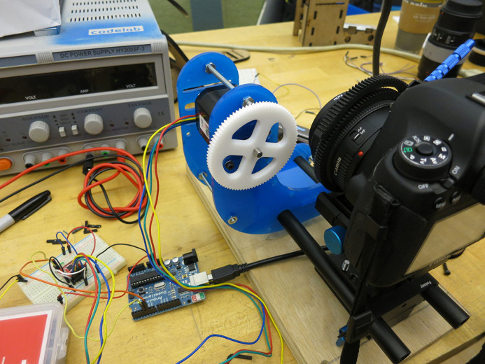
Servo driver -
Arduino testing


Space of Investigation
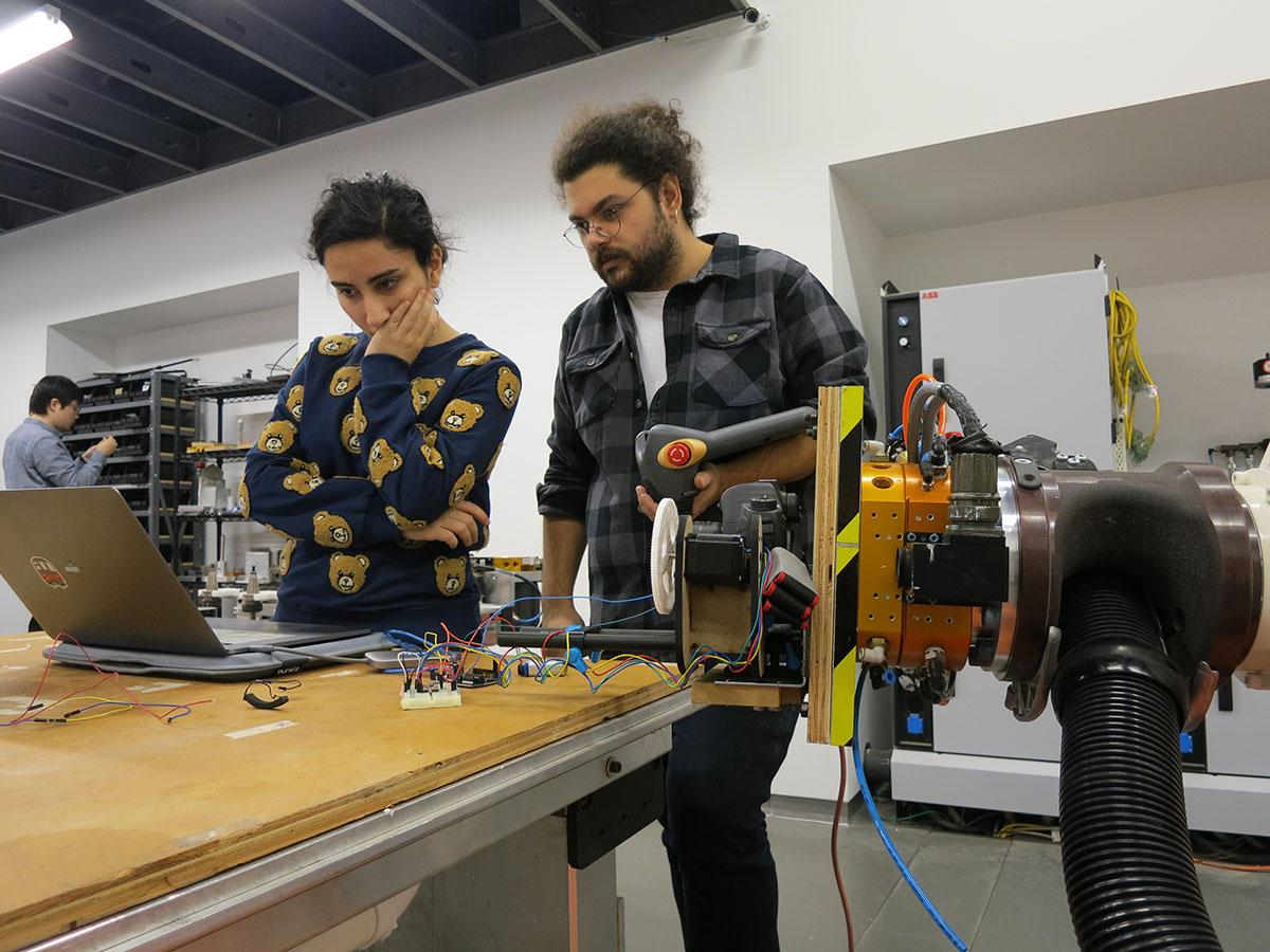
This project examines using industrial robotics for media creation, specifically DSLR video camera control and recording. Both digitally programmed camera paths and hand held capture are explored, as well as a post-process technique for VFX over the environment.
-
Lens Calibration -
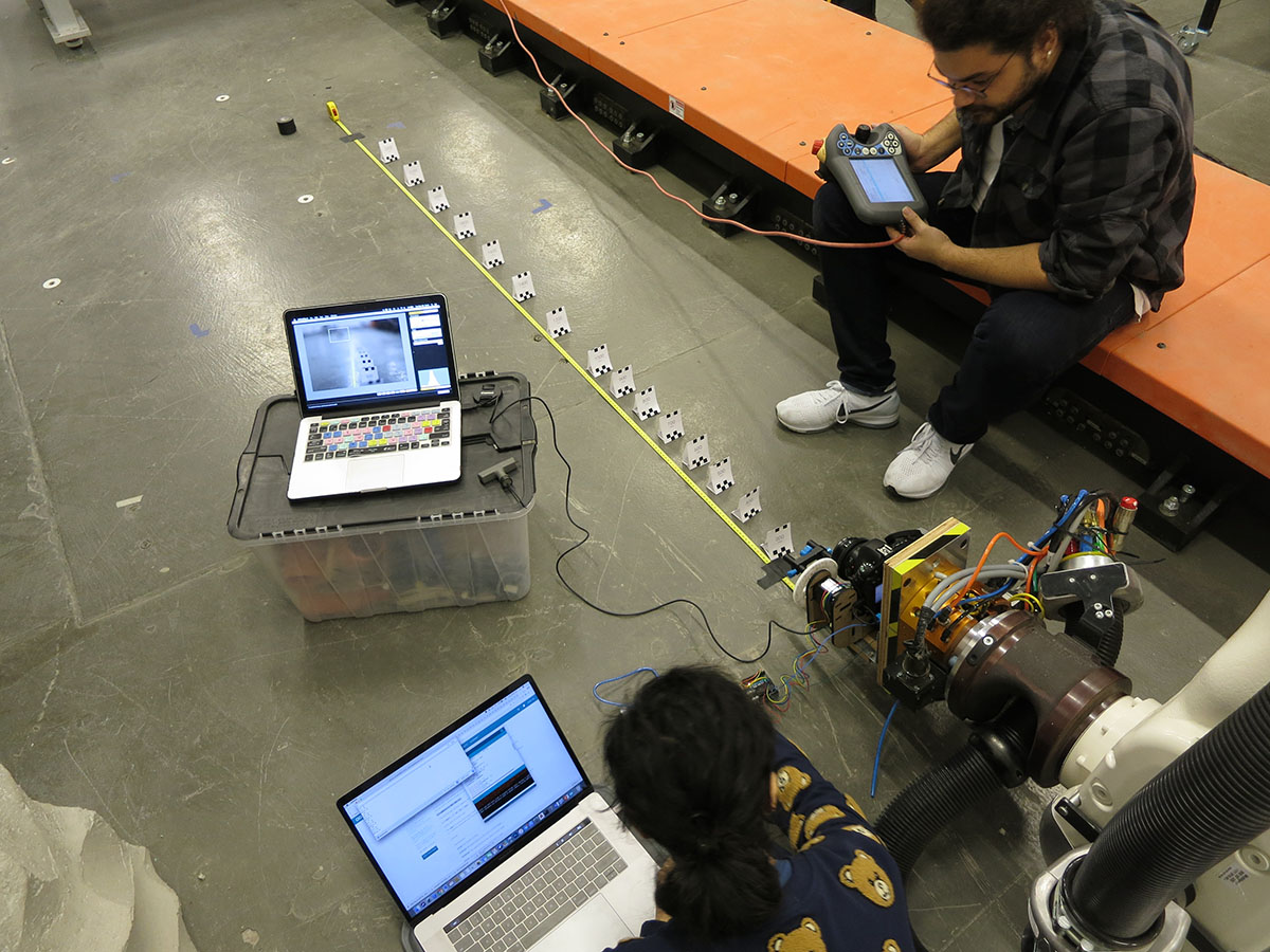
Calibration setup -

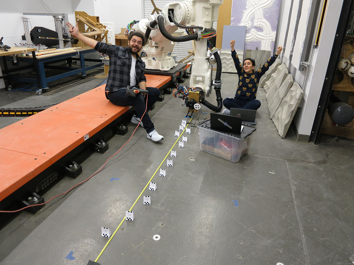
Setup -
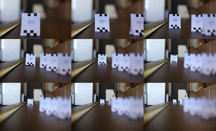
Compiled focus shots


A series of studies and experiments
Digitally controlled Camera Paths
Our first test is a simple camera-along-a-path using a curve from Rhino or Maya. This basic test is merely the baseline for video recording on the robot. Maya provides more cinematic control, as it is often used for animation and provides fine-grain motion control via a curves editor. The frame is pre-programmed as a virtual camera in this modelling software and exported as a series on planes to run as the toolpath. This camera is a ‘free camera’ and focus does not change, only position and orientation of the shot. Programming the robot for this is not challenging, and requires no digital I/O. The camera rests on a 15mm rail system that is bolted to a piece of plywood for acceptance to the robot’s ATI mounting plate.
Digitally Controlled Focal Lengths
Controlling focal length of the lens is a chief aim of this project and also us to input the point of focus as a distance, which the lens then focuses too. This requires a follow-focus (a mechanism for smooth focusing used for film), some custom gearing, and custom software. The first step is to select a lens and calibrate. DSLR lenses (we are using Canon EF-lenses) are often focused by hand, with the operator controlling the focal length by rotating the barrel of the lens to a specific depth. Our system takes a digital number of the focal distance (e.g. 1850mm) and translates it into an angle of rotation (64.5 degrees) and makes the necessary rotation on the lens.
The calibration process involves a small experiment.
(explain setup and lens marking here)
Once calibrated and programmed, the focal length is sent to the robot as a digital signal to the end-of-arm-tool. The follow focus is attached to the 15mm rails, along with the motor to drive it and an arduino to perform the translation. The end result of the digital follow focus allows us to program not just the path and framing of the camera, but a variable focus length, adjusting the point of interest in the scene with higher resolution.
The lenses we hope to use include:
NB: The macro lens is very finicky and benefits from human-hand level of finesse to capture the exact right focus. It will be very difficult to achieve this level of accuracy from the arduino follow focus but if done right could be amazing.
Mo-Cap controlled Camera
Instead of a virtually controlled camera via a 3D modeling package, we also plan on investigating a motion capture camera using the Vicon system in the robot lab. We will construct a 16:9 frame approximating the view of the camera that the director can carry around the scene. Three tracking spheres on the frame will have line-of-sight contact to the tracking system and will be recorded to 3D points over time. After some basic smoothing and throwing out erroneous data, the string of points will be converted into a curve for translation and further refinement for recording. This step breaks us free from 3D modeling as a basis of the video, and allows for haptic and hand-held control of the camera, while offering precise repeatability.
Mo-cap controlled Follow Focus
The second level of complexity of motion capture still utilizes the tracked frame, but includes another point – a sphere tracker on a telescoping pole. This enables the director (or likely an assistant) to dynamically place the sphere on the object of focus, and after recording the frame and focus sphere simultaneous, recording the scene using the follow focus from Step 2.
VFX matched into Robot Environment
Beyond controlling the camera for recording, we are also looking into adding digital visual effects in post-production over the recorded video. This becomes trivial as we already have a digital representation of the scene and camera positional information. Often without this data, VFX companies use matchmoving or structure from motion, a computer vision technique that backsolves for the position and orientation of the camera by analysing and comparing multiple frames from the sequence.
We intend to animate some simple digital objects in the scene to matte over the footage and show a proof-of-concept that 3D animation is easily overlaid onto robotically-recorded video footage.
VFX match over other Robot
The last technical hurdle we intend to vault is animating moving objects in the scene while the camera is moving. Much like the previous step, it involves compositing 3D animation, but now this 3D animation is moving, likely with or because of the other robot.
Final Film linking together all of these
The eventual result of these experiments will culminate in a short film showing of the individual technique and virtuosity of each. We plan on collaborating with a film student to generate ideas on content and story, likely focusing on the robot lab space and tools inside it.
Precedents
We looked towards a number of precedents in research, commercial practice, and the arts for inspiration. Bot & Dolly was a great company that pioneered robotic videography work and was
the largest inspiration for this project. Unfortunately they were bought by Google and never were heard from again. RIP. Their most iconic film, Box (2013), is a self-funded technical demo collaborating between Bot & Dolly and GMUNK, resulting is a mesmerizing technical demo, using illusion and magic as the context to show off their robot driven system connecting projection mapping, VFX animations, and robotic camera control. All visuals are pre-rendered and projected, captured in-camera, and not post-processed. They professionally worked on numerous commercials and film work like Gravity (2013), showing the technical feats that robotically-recorded video affords.
Robots are being used more and more to film. Kendrick Lamar’s 2017 rap video, Humble (Aftermath/Interscope 2017), has a short robotically controlled camera for a short sequence effect. Another interesting example is a type of inversion of the robot. The Mill’s Blackbird (2016) prototype is an inversion of the camera-on-robot method, where a normal video camera is recording a moving car-like robot (with multiple cameras and trackers) and VFX is matted onto the car after being tracked in 3D during the shoot.
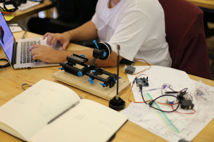
Tool Creation
Tool Prototyping
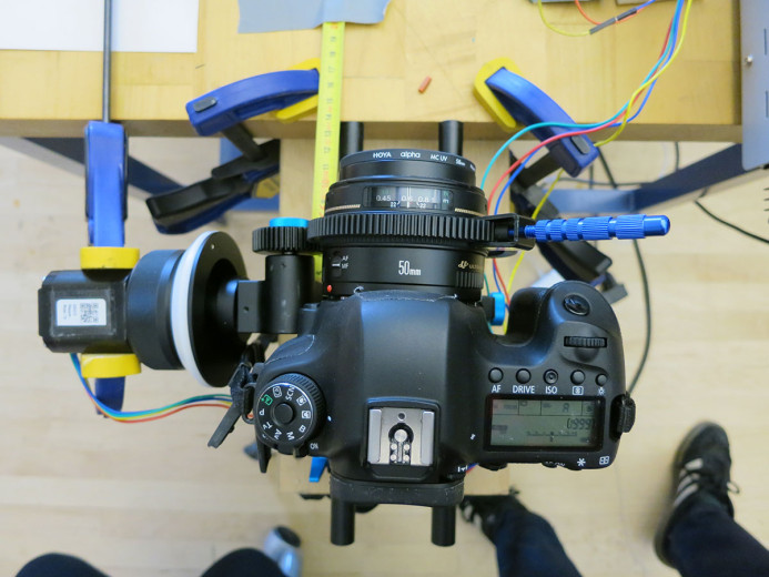
The tool is a combination of industry-standard 15mm rails, often used for mounting filters and accessories to the front of a DSLR camera, and custom electronics, all mounted on a 12” x 6” plywood base. This base holds together all of the components and mounts flush to an ATI robot arm mounting plate on the robot at typical “tool0”.
We used a cheap aluminum rail system purchased off eBay for ~$40. This included an adjustable mounting plate for the camera, two 15mm rails, and a follow focus. The follow focus is a cheaper imitation of a nicer, side-pulling manual follow focus that allowed us to quickly prototype a digital motor armature that we could program and control digitally. After some iteration prototyping on this follow-focus, we ended up deciding to design our own.
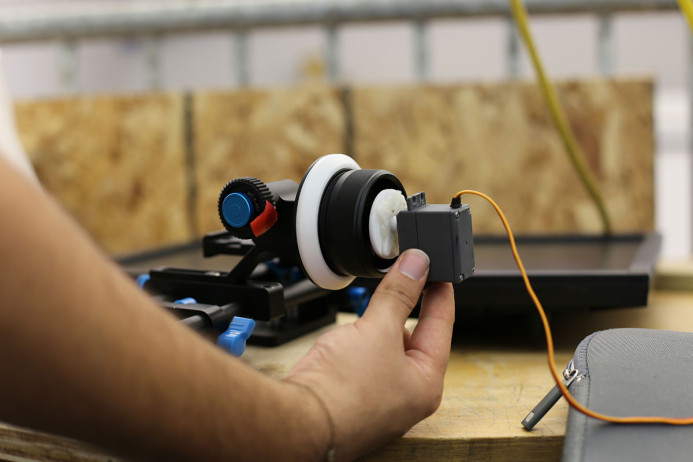
Mechanical Follow Focus
(photos of FF)
For the simplest prototypes we used an off-the-shelf follow-focus (purchased off eBay) for the gearing. Most of our initial prototyping used this set up. For the stepper and servos, we lasercut custom square driveshaft adapters to fit into the hand-driver follow focus gearing. After a number of experiments and calibrations, we decided to bypass the purchased follow-focus, and create our own. The purchased follow focus had some slop in it, in addition to being quite large. With a stepper on the side of the rig, it would make the tool fairly wide and with a large moment force on the side. To short circuit these factors, we designed a few iterations of our own gearing and stepper chassis.
(photos of our own designs here)
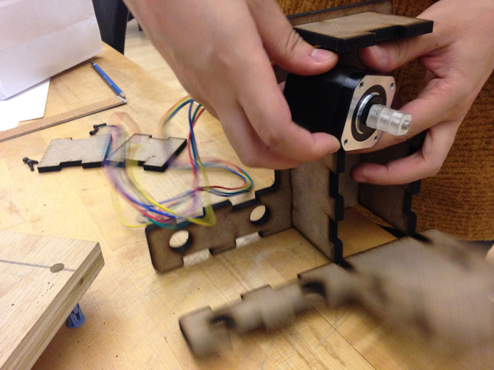
Physical Computing – Arduino Electronics
For mechanically driving the motor we started with a typical Arduino Duemilnove. With this we prototyped control using a number of different servos and stepper motors. The first servo we tried worked well immediately. The gearbox provided enough torque, even running at 5v through USB on a laptop, as well as a precise number of steps per revolution (360) and would allow us to keep track of what angle the gear is at, much like a built-in rotary encoder. The servo failed in one critical spot – a typical servo only rotates 180 degrees and back. The largest range in the lenses needed ~200 degrees, and the reduction of the size of the lens circumference to the follow focus circumference is about 4:1, meaning the full range of the servo only works for about 45 degrees. This led us to a stepper motor.
Steppers are another type of electronically controllable motor that rotates a shaft at a given step size, typically 200 steps per revolution, can rotated continuously, and are used often on CNC machines and 3D printers for gantry travel systems. These features make it ideal for this use.
Swapping out the motors we were immediately disappointed that the stepper requires more power for driving than the servo, and we moved up to an external power supply to push 12V directly to the motor. After laser cutting an adapter to drive the follow focus using the stepper shaft, we were able to set up a calibration process using incremental step input.
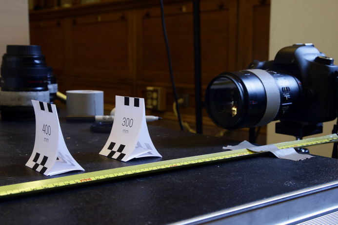
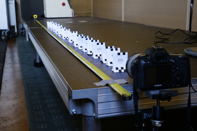
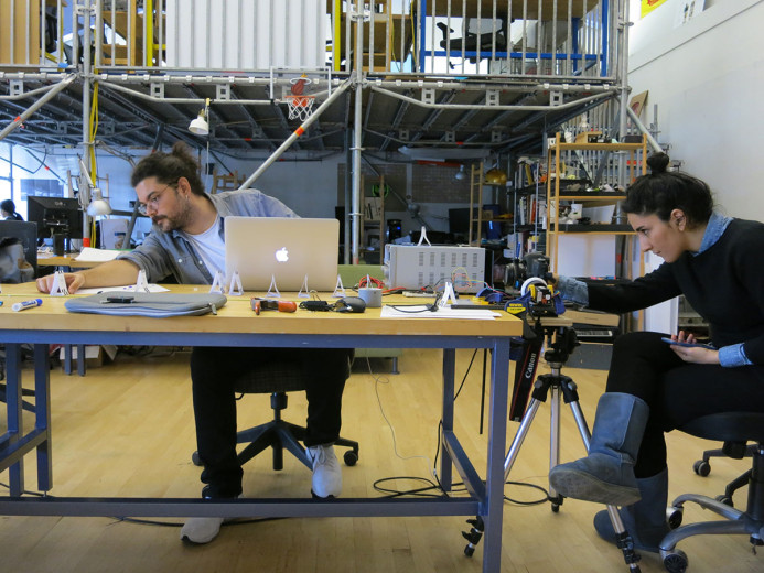
Data Translation – Calibration
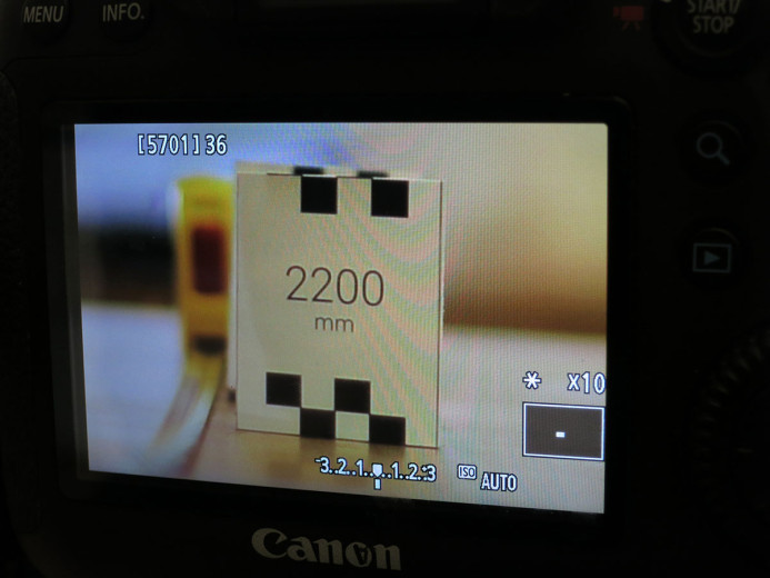
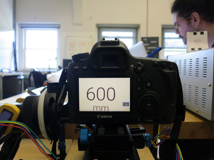
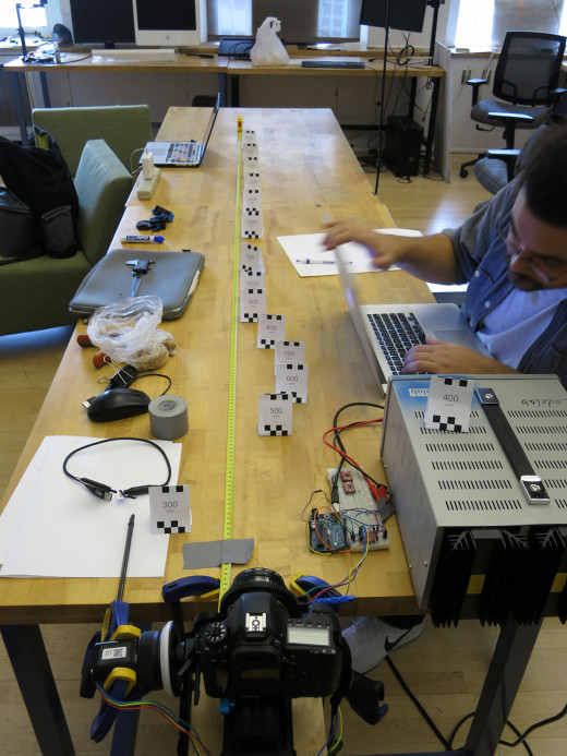
While we made a couple initial calibration studies before hooking up the motor to the follow focus, the real calibration requires the translation of digital steps controlling the motor, which in turn focus the lens. With the arduino hooked up to the stepper and the camera fixed in position on the rails, we laid out a field of markers at every 100mm from the camera sensor. The stepper is set to zero steps, and engaged with the lens gear with the lens set to its closest focus depth possible (often around 300mm).
As steps are added, one person enters steps into a command line in Arduino, adding or subtracting as needed, while another person is looking into the camera’s LCD display, zoomed into to 10x zoom, verifying the focus clarity of the stepper position. When the camera is focused precisely at a set focal distance (i.e. 600mm), the computer operator would record the number of steps from zero on the stepper, and after aggregating all of them, plot a line graph from 300mm to infinity (or 2400mm was the longest we calibrated).
-

-
test v1 -
Oz -

Focus pulling -
Macro -
-
Calibration -
Team


